Go kart projects
Below is a picture of a go kart kit that is one of the types that is easier to build. This is one of those type of kits that comes very complete and requires minimal tools and fabrication skills to build. As a minimum, you will need to supply the engine and clutch for most go cart kits. This particular example shown in the picture is sort of a on/off road go kart. It has no suspension, so this type would work best on smooth paved surfaces, grass, or smooth packed dirt.
Example of available go cart kits
Background to Wooden Go-Kart Plans
Wooden go-karts, often called go-carts or carts, are simple vehicles which are not self-propelled, threfore someone must push the go-kart and driver, or use the kart for going down hills, hence the prefix "go" is put before the kart. In these plans, spoked wheels are used, as this allows the driver to to turn the wheels by hand, much like on a wheelchair. Normally - the steering mechanism is very simple, and can be done by the drivers feet, or by using a length of rope to rotate the front axle, much like on old stage coaches seen on television. Typically on simple wooden kart, or soap-box-carts, there are no brakes, and as a result - are to be used for slow speeds only. It is possible to include brakes off a bycycle etc., however this complicates the build.The simple wooden go-kart, the plans of which can be seen below can be made by anyone. Only simple common tools are required, along with some materials easily found at home, or which can be purchased very cheaply in a DIY (do-it-yourself) , or hobby shop. The tools required to build this wooden kart are: A Hammer, A Hand Saw, An Electric Hand Drill, An Adjustable Spanner, A Measuring Tape/Ruler, and A Metal Hacksaw. The materials required are: 2" (inch) Round Nails, 5" (inch) Round Nails, Planks of 3"x4" timber/lumber, Planks of 1"x4" timber/lumber, Length of 3/4" (15mm) Diameter Round Metal Bar, 4 Spoked Wheels, Range of Washers, Range of Bolts and Nuts and Split Pins.
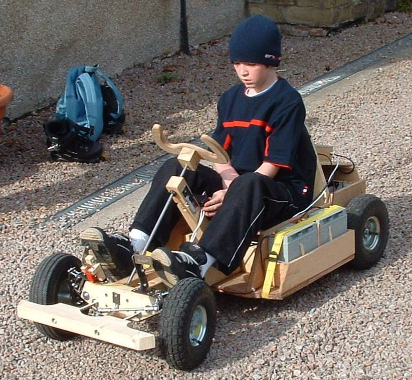
Overview of the Wooden Go-Kart :: Drg. 1
This Drawing shows the Overview of the Wooden Go-Kart. The simplicity of the go-kart can be seen, especially with the basic steering, and the sinmple planks of timber/lumber that are used. The timber/lumber is nailed together using Round Wire Nails. Wood glue could be used, however it is not necessary, and would make it very difficult to dismantle the go-kart. Where possible, protruding nails should be "clinched" to provide extra strength and safety (clinch means to bend over/flatten protruding nails).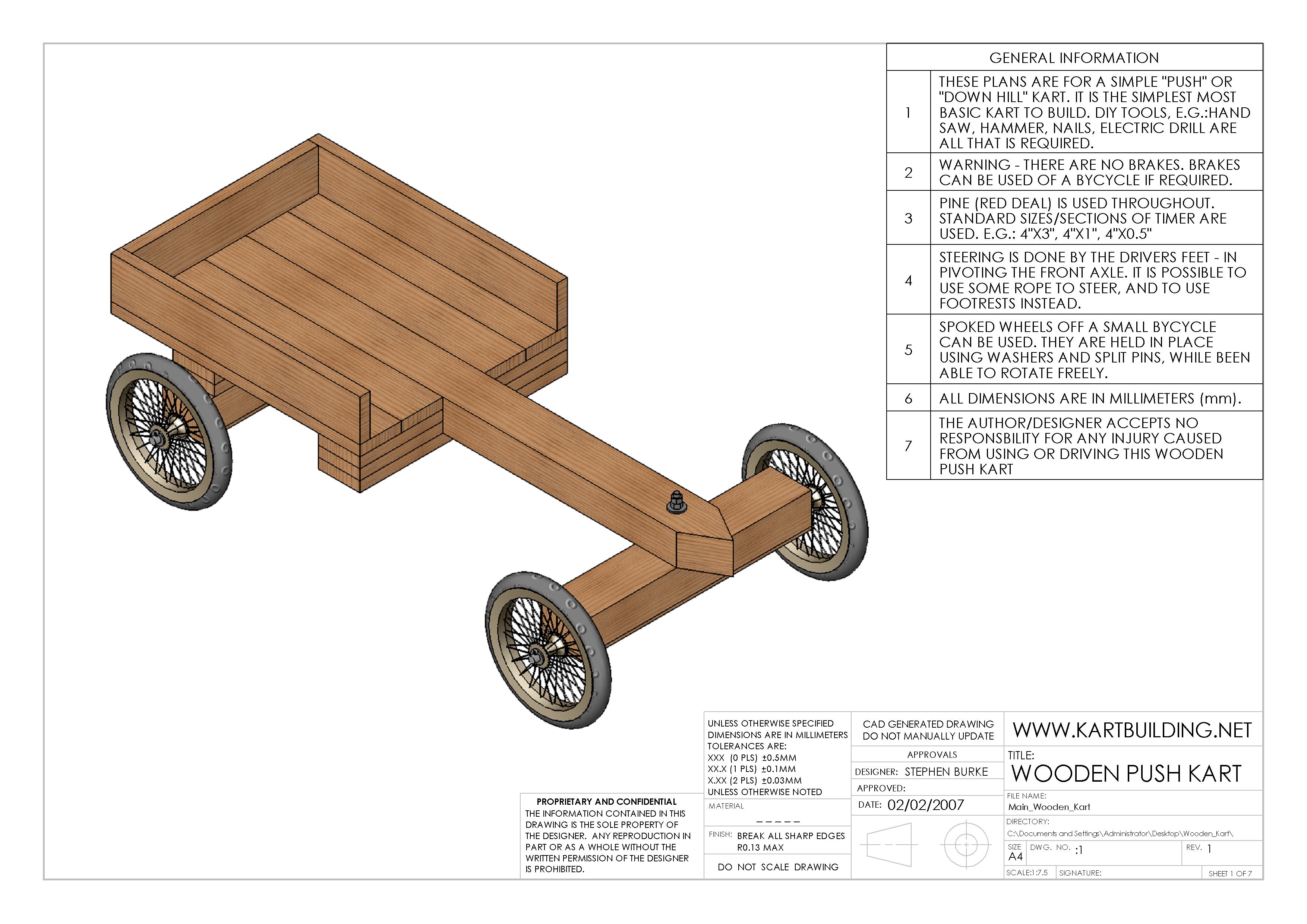
Finding/getting the spoked wheels for this go-kart is the hardest part. Once the appropriate wheels are available - making the kart is very easy and simple. Spoked wheels can be obtained of old prams. Pnuematic spoked wheels can be obtained from small childrens bycycles. It can be difficult to fit the Metal Bar/Axles through the center of these wheels, however the axle can be filed down at the end to the required diameter.
Plan, Elevation & End View of the Wooden Go-Kart :: Drg. 2
This Drawing shows some of the main dimensions/measurements for the wooden go-kart. The go-kart is approximately 1.2 meters long, by 0.7 meters wide. If required for a smaller or larger person/driver, or if a two-seater go-kart is required, the width and length of the go-kart can easily be changed to suit. The height of the kart depends largely on the diameter of the rear wheels. The larger/smaller the wheels the further/closer to the ground the go-kart is. I suggest obtaining spoked wheels of diameter 270mm.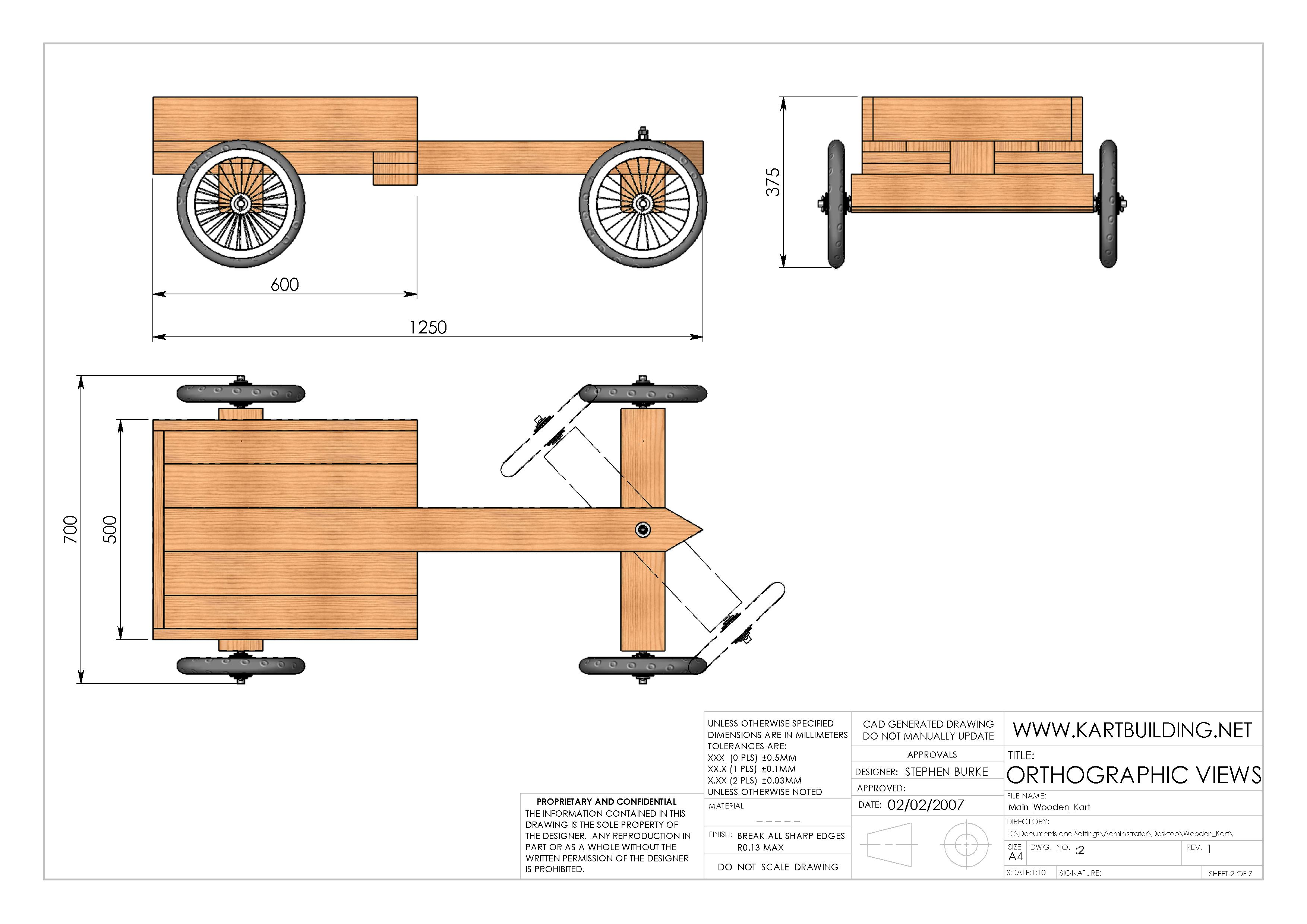
The steering or pivioting of the front axle can be also be seen in this Drawing. The front axle can be rotated left or right, and can be controlled/ operated by the drivers feet, or by a length of rope attached to either end of the front axle.
Layout and Measurements of the Wooden Chassis :: Drg. 3
Standard timber/wooden planks of 100mm (or 4") width make up the main chassis. The center chassis member is thicker and longer. The distance between the front axle and the rear of the kart is not critical, however there should be enough room for the front axle to pivot without the front wheels hitting the seating area of the wooden go-kart as seen in Drg 2.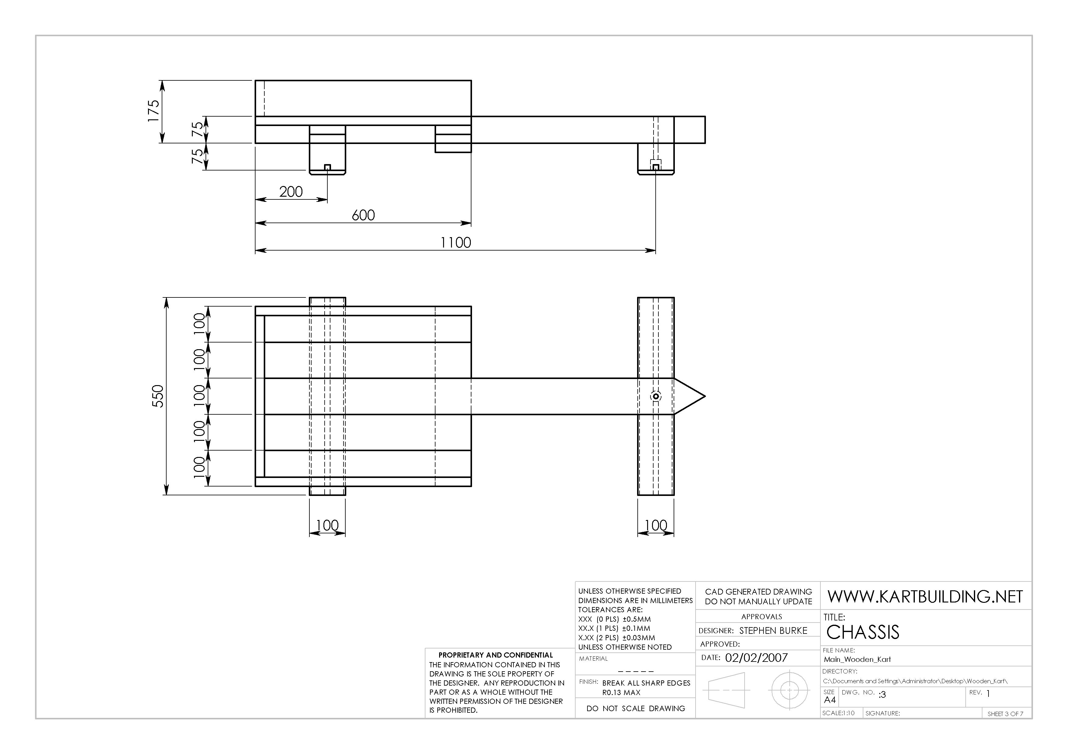
The front and rear axle support members are 100mm wide x 75mm deep (4"x3") x 550mm long. The front axle support member is connected to the chassis at the front via a 12mm Bolt, allowing it to rotate right or left. This 12mm bolt cannot be over-tightened, as the front axle will not turn freely. Instead a "lock nut" is to be used, and in this case, two nuts are used and tightened together locking them, preventing them from loosening.
Exploded View of the Wooden Go-Kart :: Drg. 4
The Assembly of the wooden go-kart can be seen in this Drawing 4. There is a flash animation on the right - showing the disassembly and assembly of the wooden go-kart showing every nut, bolt, washer and piece of timber used to make the kart.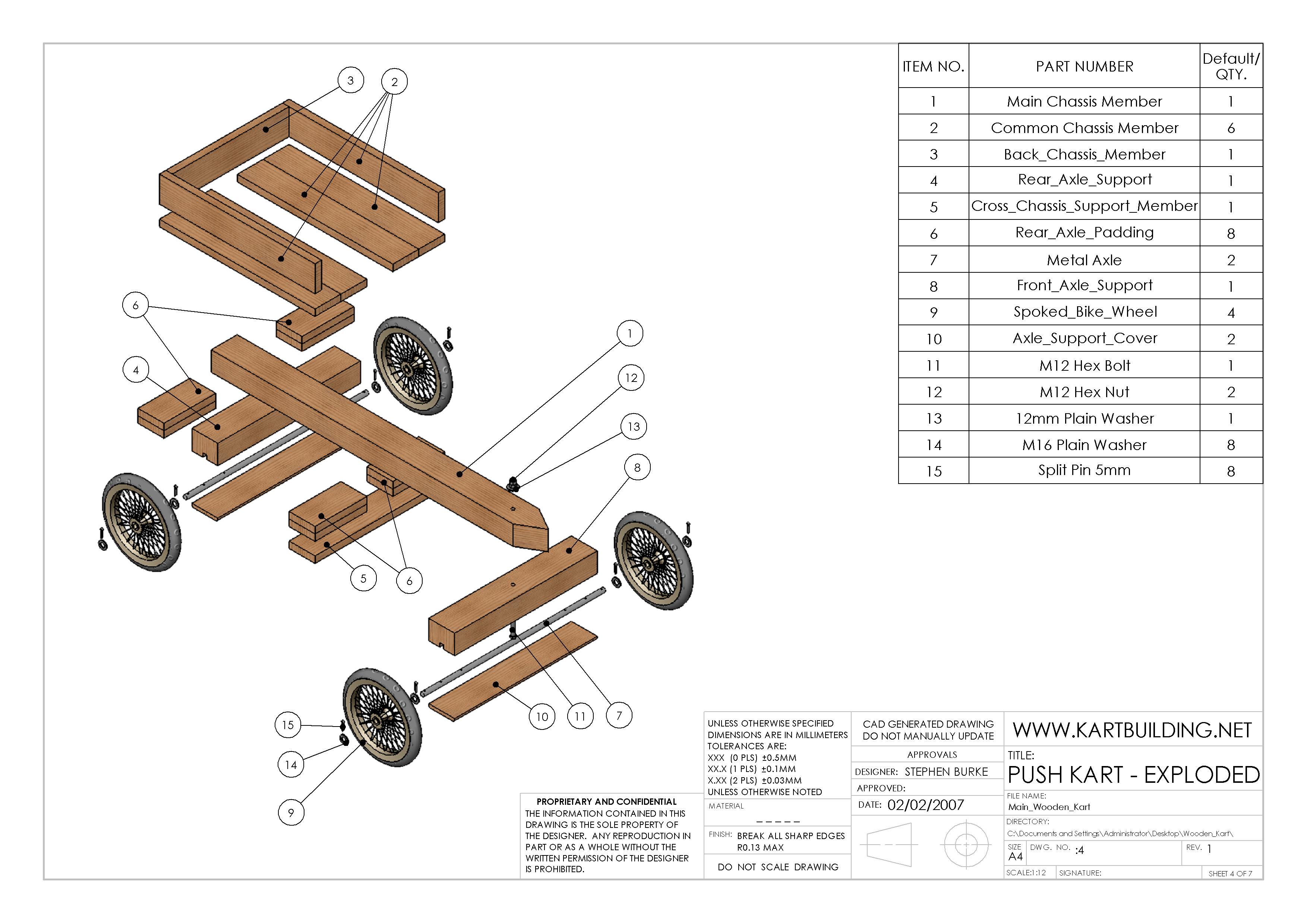
The Front and Rear Axle supports are one of the first pieces to be made. These wooden support pieces, have a groove/ slot to accomodate the Metal Axle securely. As will be seen in later detailed diagrams, there are additional holes in the middle of the Metal Axles to recieve a Round Wire nail to secure them inside the Wooden Support, and to prevent them from rotating or moving from right to left.
Detailed Part Drawings from 1-5 :: Drg. 5
Detailed diagrams of the dimensions and measurements of Items 1-5 as listed in Drawing 4 (Exploded View) are contained in this Drawing.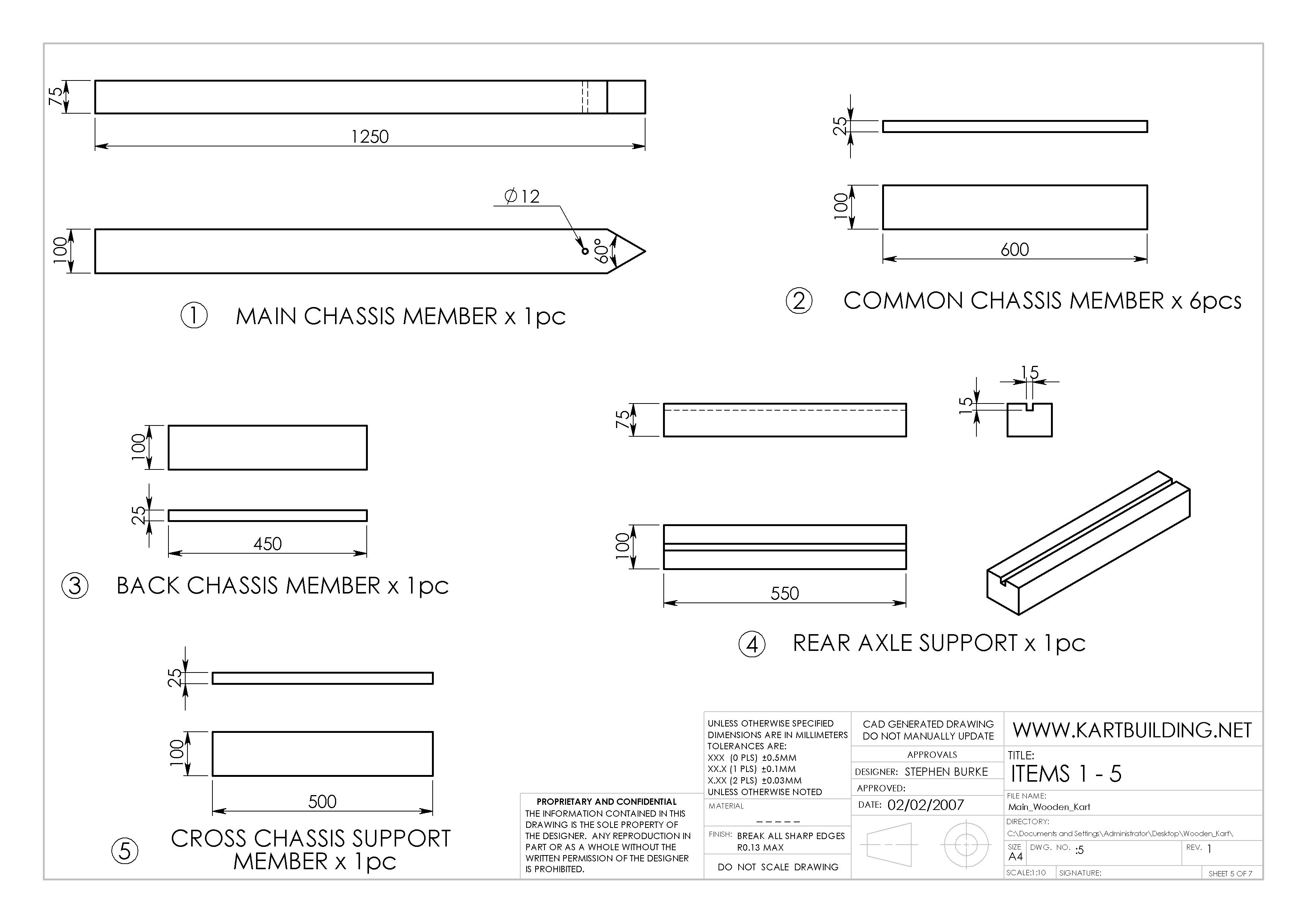
(1) Main Chassis Member: This is a piece of timber (pine etc.), 100mm x 75mm x 1250mm. The 60degree pointed front end is not essential, and can be shaped when the go-kart is finished and assembled. A front bumper or fender could be placed at this end, instead of the 60degree point.
(4) The rear axle support is made from the same size timer as for the Main Chassis Member. There is however a 15mm x 15mm square groove/slot along the length of this piece. This is to snugly accomodate the 15mm diameter metal axle. There are a few ways to remove this slot/groove:
a: Using a 15mm Mortise Chisel
b: Using a plough plane
c: Using an electric (skill) saw (set the depth to 15mm, making 4-5 parallel cuts)
d: Using an electric drill and 15mm drill bit, drill a series of holes, 15mm deep. Clean up afterwards with any chisel.
Detailed Part Drawings from 6-9 :: Drg. 6
(6) The Rear Axle Padding pieces, can best be seen in action in Drawing 4 (Exploded View). Two of these 25mm thick padding pieces amount to 50mm, and sit on top of the rear axle support, on either side of the Main Chassis Member. Longer nails will need to be used, to make sure these padding pieces are secured in place.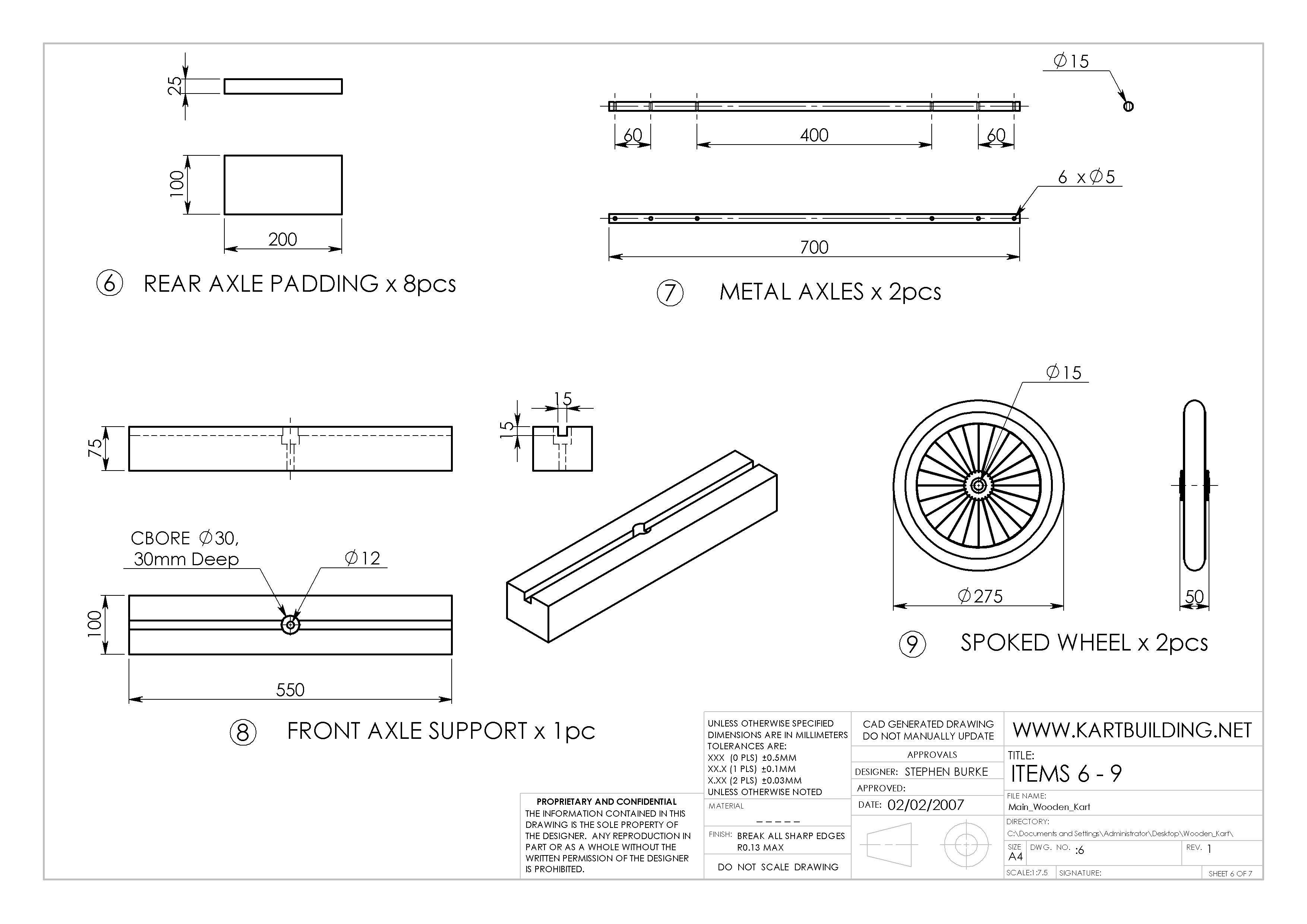
(7) The Metal Axles are simply lengths of metal bar, diameter 15mm. These can be obtained from old railings or gates, or can be purchased at a local hardware or DIY store. There are a total of four 5mm holes drilled. The middle two holes, 400mm apart, allow for the Metal Axle to be securely nailed to the Rear/Front Axle Support members. The holes at either end of the Metal Axles are to accept a "split pin", and along with a washer, help to secure the Spoked wheel onto the axle, while allowing the wheel to rotate freely. Grease should be placed on the ends of the Metal Axle where the wheel rotates, as this will prevent excessive wear. More grease may have to be applied after a few weeks of running the go-kart.
(8) The Front Axle Supports are made the exact same way as described above in Drawing 5. With the Front Axle supports however, an additional Counterbore (a large enough hole to allow the head of a bolt to go deep into the timber, underneath the Metal Axle) needs to be drilled. A large drill bit can be used. This is to allow the head of the bolt to go underneath the Metal Axle (otherwise the front metal axle would have to be in two pieces). Make sure that the M12 bolt (Drg 7.) is tightly in place, to prevent it from spinning.
Detailed Part Drawings from 10-15 :: Drg. 7
(10) The Axle Support Cover is nailed under both the Front and Rear Axle Support Members. As they serve no structural purpose, they can be cut from a thinner plank of timber (12mm or 1/2") to reduce the weight of the kart. A 5mm Chamfer/bevel can also be added.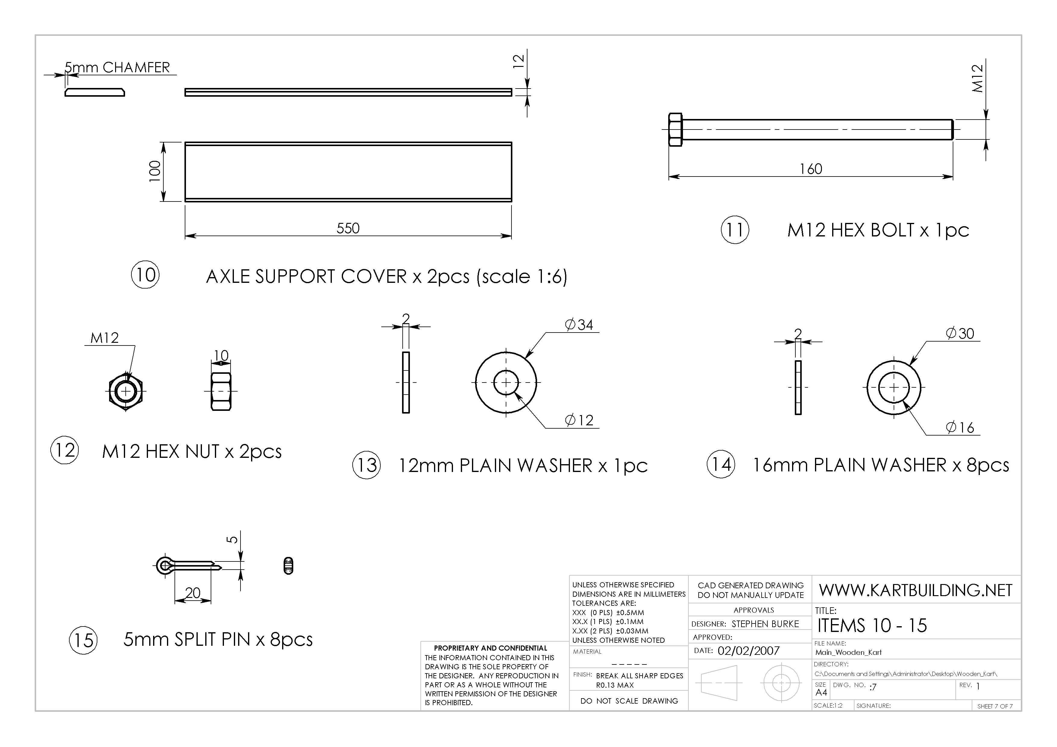
(11) The M12 (diameter 12mm) Hex Bolt, Nuts, Washers and Split Pins can be obtained from a local hardware or DIY store. Make sure that the M12 Hex Bolt (this could be a "M12 Coach Bolt either" - however is less common) is held tightly in the Front Axle Support Member (underneath the Metal Axle) to prevent it spinning. Otherwise when tighting the two M12 Hex Nuts - the Bolt may spin.
(12) Instead of using two M12 Hex Nuts to secure the M12 Bolt, allowing the front axle to turn right and left, a single special "Nylon Lock Nut" can be used to prevent itself from becoming loose due to any vibrations.
(15) A simple nail can be used instead of a special "split pin". A 5mm diameter steel nail can instead be placed through the hole, and bent at either end to form an S shape.
Final Notes and Conclusion
This is the layout for a Kart seating an average person but it is advised that you roughly lays out this design on the ground, placing a wheel at all four corners, the seat and the engine side by side. The measurements given below will not need to be altered much as there is room for movement for a bigger seat and/or bigger engine on both sides. My advice on going to construct this is to draw out the shape below on a 8 * 4 foot sheet of plywood, if your desperate you can draw it out on a strip of felt underlay with chalk. But the sheet of ply is the much better option, as you can work from this right through out the welding and bending operations what you can do is place all the sections of pipe cut to the exact length on this sheet, drive in nails both sides of the pipe and weld all the sections togethor without too much distorsion taking place. But be ware of fires. I'll take no responsibility if you burn your house down.
The most complex detail in this chassis is the pipe bending. Like myself a lot of people are not the owner of a pipe bender capable of bending 25mm mild steel tubing with a wall of 3mm. What I did an what a lot of ye will need to do is to go to your local engineering firm show him this plan and get him to bend that section out. Stay Clear of Dear Firms. One engineering firm told me that it would cost too much to set up the machine. A place down the road supplied that section of pipe and did all the bending for £30. So shop around. If desperation kicks in got to this link. Pipe bending
A welder is a necessity in this entire projct. It doesn't have to weigh a ton, a small 120 amp welder will be suffieient. I only have a 100 amp welder and I have to be very patient with it. But I got my Kart built. If all you have is a 100 amp welder or less you will definately need to use 2.5 SWG welding rods.
This is the most important section of the entire Kart, spend a good week or two making this section. Have no holes in the joints or anywhere for that matter. If this section is constructed well it will serve you for years and for a number of engines. Mine went through 4 major engine and drive changes as ca be seen in my "Pictures of various karts.." at my homepage.
This first Diagram shows the main Steering Column, with all it's supports. The Top Column Support is either a brass bushing pressed into a mild steel pipe, or simply a suitable sized steel pipe. The steering column will turn inside this and is prevented from moving by two split pins and washers. The reason the brass bushing is inside a mild steel pipe is to facilitate it's fixing to the strut, by welding. The other end of this strut can either be welded or bolted to the chassis, however this can only be done with a person sitting in the kart and to adjust the height etc. and then finally to weld it in position.
The bottom Bushing/pivot can also either be bolted or more simply welded to the chassis, all of which should be done with a person/ driver sitting in the kart. A vise-grips or a clamp can be used to keep everything in the correct position before welding. The bottom pivot can either be turned out on a lathe, or an ordinary pipe, with a suitable washer welded on.
However it is my recommendation to leave the installation of the Steering column and Drop Arm until the near end of the kart's completion. This can then be adjusted to fit everything else i.e.. drop arm, seating position, pedals.
Track Rods.
The installation and construction of these is fairly simple. Basically the rods are 16/20mm mild steel tubing, cut to the given length, with nuts (M10) welded to each end of each pipe. These nuts will receive "rose end bearings", which as well as providing a suitable fixing to the Steering Arms as well as providing a certain amount of adjustment. In the middle the Drop Arm will simply bolt to these "rose bearings". At the ends where they meet the "hub steering arm" they simply bolt together.
Once the track rods are in place the steering wheel and drop arm can be installed accordingly.
Floor Pan
It is my suggestion that the floor pan now be installed onto the kart. I recommend using "Ribbed aluminium Checker Board" (3-4mm) for the floor pan. If not 1mm mild steel sheeting will have to be used. This can easily be shaped with a "jig saw" with a steel cutting blade. The checker board can then be shaped to fit the curve nicely. If you try to use an angle grinder you WILL fail!!!. you can however if you have a few cutting disks to spare you can clean of the burr. Once the required shape is cut out, it is just a case of fixing it to the chassis.
You can just bolt the whole pan to the chassis by drilling a hole through the chassis and the pan, and fixing it on with a 5mm bolt and rubber grommet/washer. However this severely weakens the chassis, and a better option would be to weld pieces/ tags of metal to the chassis and to bolt the pan to these tags instead. Only a few are needed. It depends on the strength of the tags.
Mount the floor pan on top of the chassis. Also it would be an idea to keep some of the "aluminium Checker Board" for later, as it will be useful for the pedal floor pad, for one's feet to rest on.
Accurate Measurement is Very Important (Photo courtesy from sadik.net)
Steps on How to Build the Front A-Arms Assembly:
- Always measure the steel materials twice to make sure that the specified length is correct. Never use welded pieces for the main supporting parts.
- Use a pattern, a template, or a guide to make sure that the shape of the A-Arm is accurate and equal all over.
- Weld all joints and pieces well together. Use steel clips to keep these pieces from moving while welding.
- Use the right size of nuts to lock bolts. Do not forget to put washer in between of each nut and bolt, and joining ends of steel tubes to avoid warp and wear.
Click thumbnail to view full-size
Careful Measurement is the First Step to Perfection (Photo courtesy from sadik.net)
Steps on How to Build the Main Frame Assembly:
- Lay down the pipe steel on a clean part of your concrete floor. Be sure to measure the length and width before welding each piece.
- Use proper support to get proper height and clearance of parts to be welded.
- The body and roofing frame need bending to create round edges. Use a pattern, to be sure that all curves are equally measured.
- Arrange the bucket seats on their designated places to see how big the body size of your go-kart should be.
Click thumbnail to view full-size
Step 1
Steps on How to Build the Drive Axle Setup Assembly:
- Find a lawnmower differential with 13-teeth sprocket and 9-teeth axle.
- Link them by a type (or size) 50 chain so that the speed will get higher than what the lawnmower originally could give.
- Install a chain guard to keep chain from falling off while go-kart is running.
- Choose the appropriate sizes of bearings and tires to insure good running condition.
How to Install a Converted Rack to Go-Kart
Click thumbnail to view full-size
Converted Hyundai Excell Rack on Go-Kart (Photo courtesy from sadik.net)
Steps on How to Build the Steering System Assembly:
- Secure the steering part on the frame with use of steel clips pushed into bored holes on pipe steel.
- Use nuts and bolts where needed securing.
- The steering rack used in this go-kart is converted from a 1986 Hyundai Excell (models from 1985 to 1989 will also work).
How to Convert Hyundai Excell Steering Rack
Click thumbnail to view full-size
Step 1
- engine
- frame
- suspension
- steering
- tires and wheels
- brakes
- seats
- seat belts
- centrifugal clutch
- torque converter
FRAME
2 Types of Steel for the Go-Kart Frame:- Pipe (round) - Pipe steel on a go-kart looks neat but it is harder to manipulate and weld together.
- Square (angular) - Square steel is cheaper and easier to bend or join, but not so good to look at.
How to Weld the Go-Kart Frame
Important Points:
- You can combine pipe and square steels to create the frame for your go-kart.
- Weld all the pieces of the frame properly and accurately. Put supports where needed.
- Make sure the welded joints are tough and strong, so that they can take abuse during rough rides.
- After each test ride, carefully inspect the welded points of the go-kart to make sure that it is built to last long.
SUSPENSION
The probable role of suspension to your go-kart is to make the ride less bumpy during long travels. Some go-karts have shocks installed. But since you're not driving your go-kart to a very large distance, you might want to skip the installation of any suspension.Eliminating suspension will also save you much money. If you really want a ‘softer' ride, you have the option to put in big tires instead.
New Idea for Steering Set-Up
STEERING
Second to the engine, steering can give you some complexities while setting it up on your go-kart. The main role of steering is to keep all, rear and front, wheels aligned-and not pushed away or toward each other. A durable construction of steering wheel is absolutely important because it gives direction to your go-kart. Steering calls for some expert handling so have it assembled by your dependable mechanic. Or find and buy a new steering set-up from major parts stores.Click thumbnail to view full-size
Spindle
4 essential parts that make your go-kart easy to manipulate:
- Steering shaft - which begins with steering wheel and ends at the bottom with pitman arm.
- Spindles - are also known as axles when in the front of go-kart. The spindle is the steering connection to the axle.
- Tie rod - connects the pitman arm and the spindles. The tie rod dictates the amount of ‘toe in' for your go-kart to turn corners well.
- Pitman arm - is found at the bottom of the steering shaft. When you turn the steering wheel, the steering shaft also turns and the pitman arm attaches to tie rods to push them towards the desired direction.
Click thumbnail to view full-size
2 Piece Rim
TIRES AND WHEELS
Most go-karts use large tires at the rear. You can find different sizes of wheels that fit the 4.10x3.50 from major auto parts suppliers.Standard sizes for bearings are 5/8" and ¾". Take note that the size 5/8" has axle bolts that fits perfectly on 1-inch tubing.
Best choices:
- Ribbed tires are more resistant to traction and to wear than the knobby type.
- Tubeless tires require tubeless rims.
- High-speed bearings are also high-priced but they have better performance than the low-speed and cheaper standard bearings.
Click thumbnail to view full-size
Band Brake
BRAKES
4 Types of Brake for Go-Karts:- Scrub brake - have metal paddles that are pressed against both rear tires when the brake pedal is pressed. This brake pedal can be transformed into a hand brake but can put much pressure to tires.
- Band brake - are simple to fix and relatively cheaper but won't work well when wet. A band brake uses a metal band to squeeze around the outside of brake drum to stop motion of wheels.
- Drum brake - swells inside the brake drum to restrain movement, rather than controlling from the outside. Drum brakes are better and more durable than band brakes because they don't get wet often.
- Disc brake - is the best because it provides superior stopping ability; but also really expensive. You may use the drive sprocket as substitute to the brake disc, but it needs to be cleaned often to work properly.
SPROCKETS
A chain and sprocket are popular for the drive assembly because they perform better than the pulley system. They are also simple to set-up and a lot cheaper. For go-kart applications, the following chain sizes are good performers: #35, 40, 41, 420 pitch sprockets.Large sprockets (or drive sprockets) have better low-end power; while small sprockets (or engine sprockets) give higher top-end speed.
Small sprockets tend to weaken the low-end torque of a go-kart. To help improve its poor performance, you might want to add torque converters.
Click thumbnail to view full-size
Heavy Duty Clutch
Most vehicles/toys that children play with have steering wheels. The steering wheel in this cart comes as a welcome addition, although it requires a bit of extra work in setting up. The brake is an extra addition also, and was not included in the original set of cart plans.
This cart should be easy to build, take approximately a weekend to make, and be fun for children to drive.
Get your materials.
Import cars from US$800
Cheap Japanese used cars offer.over 500cars on sale from Japan.
www.ExportJapaneseCar.com
www.ExportJapaneseCar.com
- 2
Draw your plans for the go kart. The size you make it will depend on the age of the driver. For young drivers, about 30 inches wide by 50 inches long will work, but for adults, you will want about 40 inches by 72 inches.
- 3
Get all the parts. You may be able to salvage parts from an old riding lawnmower or a junk go kart found at a yard sale.
- 4
Obtain a welder. If you do not know how to weld, you will have to hire a welder for this project. The welds should all fit well with good quality, i.e.: proper heat, weld depth/penetration and uniform weld-beads (Otherwise, the welds may be weak, brittle, bubbly, cracked and/or only surface deep.).
- 5
Cut the metal tubing according to your design, and weld it together. For more strength, use gussets at all corners.
- 6
Assemble your steering linkage as illustrated, using the 1/2 inch steel rod for linkages, and the 3/4 inch for your axles. To make the 90 degree bends in the 3/4 rod, you may have to use a torch to heat the steel.
- 7
Take your time with designing steering to provide adjustable links for aligning steering, because it is very important to have the proper caster and camber: front-wheel vertical and steering tilt.
Caster angle is the angular displacement from the vertical axis of the suspension front to rear. Caster angles are used to improve wheel alignment for cornering.[1]
Camber angle is the basic angular displacement of the steerable wheels of a wheeled vehicle as measured when steering is adjusted toward going straight forward such that wheels may have changeable settings of the tilt off of the vertical or horizontal.[2]
- Toe-in versus toe-out is another setting displacement off of straight forward alignment. Compare this to having pigeon-toes (big toes pointed inward) versus spraddle feet (feet pointed outward).[3]
- 8
Build your axle with a straight piece of 3/4 steel rod, and two bushings attached to your frame. Use washers and cotter pins drilled through the axle to keep the assembly in position.
- 9
Attach the drive pulley on the axle prior to mounting the axle in the bushings. You can either use a set screw to hold it in position, or weld it directly to the axle, but it should be aligned with the pulley on your engine.
- 10
Weld a flat piece of 3/16 inch steel plate to the rear frame to mount your engine. Place the engine on the plate, and mark the holes for mounting bolts so that the engine pulley lines up with the drive pulley on your axle.
- 11
Attach the throttle cable to the hand throttle, or a linkage for a foot throttle (not shown, optional).
- 12
Build your seat and floor boards out of plywood lumber or metal, roughly as shown in the illustration.
AZ3502 - Go Kart Frame w/Steering Hoop (actual shipping charges apply)
This sturdy, double tube construction, high quality unit is jig-welded and made of 1" x .083" wall tubing. Complete with steering hoop assembly, belly pan, engine mounting plate, spindle brackets, steering shaft bushing, pedal bushings, live-axle bearing hangers and control rod anchors. Most components needed to finish the go-kart are available from us. No additional welding needed. Well designed and rugged, the frame weighs just 31 pounds. Actual Shipping Charges Apply
This sturdy, double tube construction, high quality unit is jig-welded and made of 1" x .083" wall tubing. Complete with steering hoop assembly, belly pan, engine mounting plate, spindle brackets, steering shaft bushing, pedal bushings, live-axle bearing hangers and control rod anchors. Most components needed to finish the go-kart are available from us. No additional welding needed. Well designed and rugged, the frame weighs just 31 pounds. Actual Shipping Charges Apply
Build a go kart and power it with an electric motor.
You can get a go kart kit, that has everything but the drive system. That's probably better than trying to build one yourself, because if you build it yourself you won't get it precise to within a few thousandths of an inch like the kit ought to be. Plus the guys that built the kit already figured out all the geometry through a lot of trial and error that you won't have to go through, and they know it works.
If you build it yourself, I recommend a single front wheel, to save yourself the hassle of all the front suspension intricacies. If you try to use 4 wheels, chances are, only 3 are going be on the ground at any moment, like a wobbly table, unless you use a sprung suspension.
You know what? I recommend a single rear wheel as well. 2 rear wheels is only good on slippery surfaces, like dirt, unless you use a differential, or independent drive to each wheel, or only drive one of the 2 wheels.
If you decide to only use 2 wheels it will be easy to find a complete rolling chassis for cheap, a bicycle. You could probably find one of those cheap wal mart full suspension mountain bikes at a yard sale. You know, the kind that are too heavy to actually ride so the owners regret having ever bought them and just want to get rid of them? Turns out, they're perfect for making into motor driven cycles.
remove the left crank arm and cut the right one off. Mount some foot pegs. Use a 72 volt, 300 amp motor and mount the motor to the frame. Bolt on a 12 tooth sprocket to the motor shaft. Drive the large chain ring with the motor and drive the wheel with the small chain ring. 2 chains in total. Make a bracket to mount the batteries and drive electronics to the frame. Mount a twist throttle to the handle bars and wire it all together.
Hold on tight, it's going to be fast! Be careful not to burn up your tire, or r How would I build an electric go-kart?
remove the left crank arm and cut the right one off. Mount some foot pegs. Use a 72 volt, 300 amp motor and mount the motor to the frame. Bolt on a 12 tooth sprocket to the motor shaft. Drive the large chain ring with the motor and drive the wheel with the small chain ring. 2 chains in total. Make a bracket to mount the batteries and drive electronics to the frame. Mount a twist throttle to the handle bars and wire it all together.
Hold on tight, it's going to be fast! Be careful not to burn up your tire, or rip the chain right in half.
http://www.electricmotorspo rt.c
Hold on tight, it's going to be fast! Be careful not to burn up your tire, or rip the chain right in half.
http://www.electricmotorspo rt.c
Best Answer - Chosen by Asker
Build a go kart and power it with an electric motor.
You can get a go kart kit, that has everything but the drive system. That's probably better than trying to build one yourself, because if you build it yourself you won't get it precise to within a few thousandths of an inch like the kit ought to be. Plus the guys that built the kit already figured out all the geometry through a lot of trial and error that you won't have to go through, and they know it works.
If you build it yourself, I recommend a single front wheel, to save yourself the hassle of all the front suspension intricacies. If you try to use 4 wheels, chances are, only 3 are going be on the ground at any moment, like a wobbly table, unless you use a sprung suspension.
You know what? I recommend a single rear wheel as well. 2 rear wheels is only good on slippery surfaces, like dirt, unless you use a differential, or independent drive to each wheel, or only drive one of the 2 wheels.
If you decide to only use 2 wheels it will be easy to find a complete rolling chassis for cheap, a bicycle. You could probably find one of those cheap wal mart full suspension mountain bikes at a yard sale. You know, the kind that are too heavy to actually ride so the owners regret having ever bought them and just want to get rid of them? Turns out, they're perfect for making into motor driven cycles.
remove the left crank arm and cut the right one off. Mount some foot pegs. Use a 72 volt, 300 amp motor and mount the motor to the frame. Bolt on a 12 tooth sprocket to the motor shaft. Drive the large chain ring with the motor and drive the wheel with the small chain ring. 2 chains in total. Make a bracket to mount the batteries and drive electronics to the frame. Mount a twist throttle to the handle
This project was popular with the kids - it's a 2 x 250 Watt electric motor driven kart and got a lot of use before they grew too big for it.
As with most of the kids' buggies my aim was to try to build the kart using mainly non-specialised tools and materials. The main structure is glued and screwed timber and other features include ackerman geometry steering, rear band brakes, rear wheel drive differential action and forward and reverse drive..
The propulsion is from a rear mounted two stage reduction gearbox which has built-in band brakes direct acting on the wheel axles. Several key strength components of the kart are made of steel and throughout I've made use of standard stock engineering components such as bearings, bright steel bar, steel flat, gears, sprockets etc. Importantly, the design includes padded seat cushions... mustn't forget rider comfort!
The gearbox design is described in more detail here - it is powered by two 250W permanently engaged (no free-wheeling) 24V DC PM electric motors. It is efficient, reversible and back-driveable and, with the right choice of motor controller, can provide some re-generative dynamic braking for the kart i.e. the motors slow the kart and the energy produced is passed back into the batteries. Built-in band brakes act directly on the drive axles and provide the main mechanical braking independently of the electric drive. The independent drive to each rear wheel provides effective differential action when turning and traction from both rear wheels allows driving on mown grass, hard gravel drives etc.
They are relatively efficient (75 - 85%), especially some of the larger power units, they can be driven in both forward and reverse at variable speeds and come with a radial load bearing output shaft and usually with a roller chain drive sprocket ready to be mounted on your transmission. This is an attractive package for the DIY vehicle builder. For the designer it is also possible to obtain technical performance data for the motors directly from the manufacturer's web site - try here (loading of this site can be slow). Powers available range from 250W up to 1200W per motor for 24V, 36V and even 48V DC supplies. Most of the motors I've used from this range have rated speeds between 2500 and 3000 rpm and as such are not suitable for direct connection on to drive wheels - this has to be done with at least one (possibly two) speed reduction stage(s) to bring the speed down and the torque up to that required at the wheel. However a number of these motors are available with built-on gearheads and these versions are an attractive alternative to a DIY speed reduction build.
Mounting method depends on the motor, as you can see some have mounting feet attached, the larger motors (above right) can be front or rear face mounted or conveniently can be secured to a support using large diameter hose (jubilee) clips, see left. This by far is the easiest way to secure them - check out the plumbing/central heating section at your local DIY store for large hose clips.
It is worth mentioning that all these motors will generate heat as a natural by-product of their operation and will heat up in use, especially when run hard. Surface temperatures can easily become too hot to touch comfortably and care should be taken. In particular they should be mounted where a cooling flow or air can be provided - it is best not to fully enclose them although it is wise to provide some form of weather protection for types with end face ventilation holes.
The motors shown are from the MY1016 and MY1020 families of electric motors made by Unite Motor Co. in China and widely imported for electric scooter and trike spares. Check the suppliers page for some sources of these motors.
Electric motors with integral gear heads are also available and can simplify the transmission design in some projects. On the DIY motion Cockpits I've used 24V 200W Unite motors with worm gear boxes to provide some degree of load-holding when the power is removed. These give a compact high speed reduction design that can be very useful. Motors with worm gearing can have fairly large reduction ratios and generally the bigger the reduction the more the tendency for the gearbox to resist back driving from its output shaft. In vehicle applications this can be a problem if you are looking for the motors and electrical drive to give smooth braking response. Other gear head motors will use other gear types, eg single or double straight spur gear reductions and these will tend to have a lesser speed reduction but are more capable of being back driven and may be a better choice for dynamic/regenerative braking in electric vehicles.
No comments:
Post a Comment